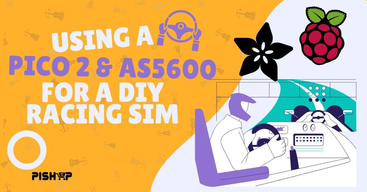
Building a Custom DIY Sim Racing Wheel with the Adafruit AS5600 & Raspberry Pi Pico 2
3D Printing, Beginner, Intermediate, Other, PiShop, Platforms, Projects, Resources, Robotics, Skills, Tutorial 3d printing, adafruit as5600, racing gaming sim, raspberry pi, raspberry pi pico, raspberry pi pico 2, sensors, Tech 0
Last week we shared an article tutorial about using the Adafruit AS5600 Magnetic Angle Sensor with a Raspberry Pi Pico. Wiring it over STEMMA QT, pulling raw angle values into Circuitpython then turned it into a simple volume knob as a proof of concept. What we love most about this sensor is that it’s a hall effect sensor, meaning it’s contactless. This makes it a perfect addition to our gaming hardware series!
We took it a step further from a simple volume knob to a fully functioning Racing Sim steering wheel along with 7 tactile buttons. Using some spare CNC hardware and a Raspberry Pi Pico 2 but saying is much easier than doing and that’s a lesson that I absolutely learnt during this project. This project ultimately turned into a deep dive into USB HID internals, device caching on Windows and the physics of magnetic fields.
What You'll Need
I used pretty much anything that I could get my grubby hands on for this project but here’s a detailed list of what you’d need to replicate this project:
Hardware Assembly and Sensor Alignment
I used pretty much spare parts laying around the warehouse however the kit that I linked includes exactly what you’ll need. The foundation of this project relies pretty heavily on the lead screw and bearing seats, this will function as our axel and where we’ll mount the whole thing down.
- Pass the T8 lead screw through the two bearing seats and mount those down onto some wood or something. This’ll create a solid steering column to handle any side-load pressure.
- I used a clamp adapter that I designed and 3D printed to fit the magnet in. attach the clamps on both ends of the rod. the magnet should be on one end and the steering wheel on the other.
- Using a 3D print I designed to hold the AS6500 I attached it, at most, 3mm away from the magnet end of the axel. This ensures that measurements are accurate.
- Wiring the I2C and GPIO Connections
- Connect the AS5600 SCL to GP1, SDA to GP0 or if you’re using a STEMMA QT connection like I am, plug the red jumper into pin 36, the black jumper into ground, yellow jumper to pin 2 and blue jumper to pin 1.
- Wire the tactile buttons between GPIO pins ( I used GP6 to GP13)
The Code
I tested most of this out using a free game called RaceRoom on steam but it should work with anything else you plan on playing. To make these games recognize the Pico 2 as a native USB Wheel we had to split our software into 2 files: boot.py and code.py. You can find all the files you’ll need below or on our github repo!
A DIY Racing Sim Rig using components from Raspberry Pi and Arduino with sensors such as the Adafruit As5600
Declaring the USB Descriptor (boot.py)
At startup, boot.py overrides the standard USB profile and presents the Pico 2 to your computer as a clean, 8-bit unsigned HID Gamepad.
					import usb_hid

gamepad_descriptor = bytes((
    0x05, 0x01,        # Usage Page (Generic Desktop Controls)
    0x09, 0x05,        # Usage (Gamepad)
    0xa1, 0x01,        # Collection (Application)
    0x85, 0x04,        #   Report ID (4)
    0x05, 0x09,        #   Usage Page (Button)
    0x19, 0x01,        #   Usage Minimum (Button 1)
    0x29, 0x10,        #   Usage Maximum (Button 16)
    0x15, 0x00,        #   Logical Minimum (0)
    0x25, 0x01,        #   Logical Maximum (1)
    0x75, 0x01,        #   Report Size (1)
    0x95, 0x10,        #   Report Count (16)
    0x81, 0x02,        #   Input (Data,Var,Abs)
    0x05, 0x01,        #   Usage Page (Generic Desktop Controls)
    0x09, 0x30,        #   Usage (X)
    0x09, 0x31,        #   Usage (Y)
    0x09, 0x32,        #   Usage (Z)
    0x09, 0x35,        #   Usage (Rz)
    0x15, 0x00,        #   Logical Minimum (0)
    0x25, 0xFF,        #   Logical Maximum (255) <-- Force pure 0-255 scale
    0x75, 0x08,        #   Report Size (8)
    0x95, 0x04,        #   Report Count (4)
    0x81, 0x02,        #   Input (Data,Var,Abs)
    0xc0               # End Collection
))

my_gamepad = usb_hid.Device(
    report_descriptor=gamepad_descriptor,
    usage_page=0x01,
    usage=0x05,
    report_ids=(4,),
    in_report_lengths=(6,),
    out_report_lengths=(0,),
)

usb_hid.enable((my_gamepad,))
Sensor Processing (code.py)
This script reads the 12-bit angle from the AS5600 and applies an offset so that the dead-center is 127, scales it down to an 8-bit range, packs the button press states into bitwise bytes, and dispatches standard USB reports at 100Hz. What a mouthful.
					import board
import busio
import digitalio
import time
import usb_hid
import adafruit_as5600

# 1. HARDWARE SETUP (STEERING WHEEL & BUTTONS)

# Connect AS5600 SCL -> Pico GP1, SDA -> Pico GP0
i2c = busio.I2C(board.GP1, board.GP0)
as5600 = adafruit_as5600.AS5600(i2c)

def setup_btn(pin):
    btn = digitalio.DigitalInOut(pin)
    btn.direction = digitalio.Direction.INPUT
    btn.pull = digitalio.Pull.UP
    return btn

# Streamlined 8-Button Layout (GP6 through GP13)
btn1 = setup_btn(board.GP6)
btn2 = setup_btn(board.GP7)
btn3 = setup_btn(board.GP8)
btn4 = setup_btn(board.GP9)
btn5 = setup_btn(board.GP10)  # Shifter Left (Via slip ring)
btn6 = setup_btn(board.GP11)  # Shifter Right (Via slip ring)
btn7 = setup_btn(board.GP12)
btn8 = setup_btn(board.GP13)

# 2. DATA SCALING FUNCTIONS

def scale_wheel(val):
    REVERSED = False
    wheel_offset = 2048  # Aligns your AS5600's physical midpoint

    # Process the raw reading against the center midpoint
    calibrated_val = (val - wheel_offset) % 4096

    if REVERSED:
        calibrated_val = 4095 - calibrated_val

    # Scale 0-4095 directly to a hard 0-255 byte array layout.
    # Center is mathematically locked around 127.
    s = int((calibrated_val / 4095) * 255)

    # Hardware clamp to prevent any out-of-bounds rollover
    if s < 0: s = 0
    if s > 255: s = 255

    return s

# Find the Gamepad device Link
gamepad_dev = None
for device in usb_hid.devices:
    if device.usage == 0x05:
        gamepad_dev = device
        break

print("Streamlined 8-Button Racing Wheel Script Active!")

# 3. MAIN RUNTIME LOOP

while True:
    if gamepad_dev:
        # 1. Fetch the raw angle from the AS5600 sensor
        raw_angle = as5600.angle

        # 2. Keep the hardware clamp filters
        if raw_angle < 10: raw_angle = 0
        if raw_angle > 4085: raw_angle = 4095

        # 3. Process the cleaned data through your signed scale function
        x1 = scale_wheel(raw_angle)

        # 4. Clear unused extra joystick channels to neutral center (0)
        y1, x2, y2 = 0, 0, 0

        # 5. Pack your 8 breadboard buttons into the first byte
        b_low = 0
        if not btn1.value: b_low |= 0x01  # Button 1
        if not btn2.value: b_low |= 0x02  # Button 2
        if not btn3.value: b_low |= 0x04  # Button 3
        if not btn4.value: b_low |= 0x08  # Button 4
        if not btn5.value: b_low |= 0x10  # Button 5
        if not btn6.value: b_low |= 0x20  # Button 6
        if not btn7.value: b_low |= 0x40  # Button 7
        if not btn8.value: b_low |= 0x80  # Button 8

        # Second byte is empty now since we only need 8 buttons
        b_high = 0

        # 6. Assemble and dispatch report
        # CRITICAL FIX: The first element in the array MUST be the Report ID '4'
        # to unlock communication with your custom boot.py setup!
        report = bytearray([b_low, b_high, x1, y1, x2, y2])

        # ... your existing code ...
        # 6. Assemble and dispatch report
        report = bytearray([b_low, b_high, x1, y1, x2, y2])

        # --- ADD THIS PRINT LINE FOR DIAGNOSTICS ---
        print(f"X1 Byte: {x1}")

        try:
            gamepad_dev.send_report(report)
        except:
            pass

        try:
            gamepad_dev.send_report(report)
        except Exception as e:
            pass

    # Keep that 100Hz polling rate locked down for RaceRoom compatibility!
    time.sleep(0.01)
What I Learnt and Troubleshooting
Building these custom USB hardware devices usually comes paired with some fun engineering hurdles along as you go:
- Upgrading mid-project from a Pico H (RP2040) to the Pico 2WH (RP2350) changed the hardware Product ID (PID) seen by Windows. Clearing out greyed-out ghost devices in Device Manager gave Windows a clean slate to recognize the new updated HID descriptor.
CircuitPython expects integers to be cleanly packed into unsigned bytes (0-255). By scaling the AS5600’s 0-4095 range so that dead-center sits mathematically at 127, turning left smoothly drops toward 0 while turning right climbs toward 255.
In games like RaceRoom, make sure to turn the wheel all the way through its full range of motion during the in-game keybinding prompt so the input configuration wizard properly detects the active axis direction! This one gave me some serious headaches before I realised it was the issue.
Conclusion
So that’s that … for now. I seriously enjoyed this project, it tested quite a few areas in my skills that I wasn’t too confident in as well as learning some new techniques that I’ll be applying in future projects. Right now my goal is to get a full Racing rig setup so the next part is probably going to be pedals. I’m currently debating on whether I should more AS5600s or just switch to potentiometers, there a pretty harsh difference in price unfortunately.
Anyway, have you created your own racing rig before? If you have, share some tips and tricks or issues you’ve come across in the process down in the comments below!
What’s Next?
With an AS5600 handling rotational tracking, you get a zero-friction steering wheel that will never suffer from potentiometer wear or dead-zone drift.
If you want to take a project like this even further, you can explore adding analog throttle and clutch pedals using additional AS5600 sensors or 10k linear potentiometers plugged into the Pico 2’s ADC pins (GP26 and GP27). For full Force Feedback (FFB) that physically turns the wheel during a crash, you can step up to an external 24V power supply, a high-current H-bridge driver like the BTS7960, and an open-source firmware suite like OpenFFBoard!