Frictionless Rotation: Getting Started with the Adafruit AS5600 Magnetic Angle Sensor
Arduino, Beginner, Home Automation, Intermediate, Other, PiShop, Platforms, Projects, Raspberry Pi, Raspberry Pi Pico, Resources, Robotics, Skills, Tutorial as5600, getting started, intermediate, raspberry pi, sensor, sensors, Tech 0
If you’ve ever had a potentiometer go scratchy after a year of use, or watched a rotary encoder’s contacts wear down until it starts skipping steps, you already know the weak point of most rotational sensing: physical contact. Wipers wear out. Contacts get dusty. Mechanical parts eventually fail.
The Adafruit AS5600 Magnetic Angle Sensor sidesteps that problem entirely by not touching anything at all. It senses rotation through a magnetic field, which means there’s no wear, no noise from dirty contacts, and, for a lot of projects, a much longer service life.
Here’s what it is, how it works, and how to get one running on your next build.
What is the AS5600?
At the heart of this breakout board is the ams AS5600, a magnetic position sensor chip. Instead of relying on a mechanical wiper or optical disc, it detects the orientation of a rotating north/south magnetic field from up to 3mm away from the chip itself, no physical connection needed.
This gives you the best of two familiar worlds:
- Like a rotary encoder, it can spin freely through a full 360° with no end stops.
- Like a potentiometer, it gives you absolute position – the sensor always knows exactly where the magnet is pointing, rather than just tracking relative movement.
The result is a sensor that reports rotation as an angle from 0° to 359°, with 0.1° resolution and 0.4° accuracy. That’s precise enough for volume knobs, joint-angle sensing in robotics, or any application where you need to know exact position, not just “it moved.”
Board Features
This Adafruit AS5600 breakout keeps things simple:
- STEMMA QT / Qwiic connector – solder-free I2C wiring. Just plug in a cable and you’re connected to power and data.
- Breadboard-friendly header – a small strip of header pins is included, though light soldering is required if you want to use it on a breadboard.
- Compact, fully assembled board – no extra components to source to get it running.
How It Works
Setting Up The Magnet
The sensor itself doesn’t do anything without a magnet to read. You’ll need a small rare-earth magnet mounted near the center of the chip, close enough that the sensor can pick up its field as it rotates.
One detail that trips people up: many round magnets have their north and south poles on the flat faces (like a coin), not around the edge. For the AS5600 to read rotation correctly, the magnet needs to be oriented so the poles are arranged across the chip as it spins, which usually means mounting the magnet on its edge relative to the sensor, not flat against it. It’s worth test-fitting your magnet before committing to a final mechanical design.
Connecting It Up
The AS5600 communicates over I2C, which keeps wiring minimal, just power, ground, and two data lines.
Thanks to the STEMMA QT connector, you can skip the soldering altogether if you’re working with a compatible microcontroller. Just grab a STEMMA QT (or Qwiic-compatible) cable, note that one isn’t included with the board, so add one to your cart if you don’t already have a stash, and plug it straight into your board.
Driver support is available for:
- Arduino
- Python
- CircuitPython
That means whether you’re prototyping on a Raspberry Pi, running CircuitPython on a microcontroller board, or working in the Arduino IDE, there’s a driver ready to handle the I2C communication so you can just read angle values directly.
Example Use Cases
https://hackaday.io/project/191652-long-range-weather-station-65/log/220476-the-wind-direction-sensorBecause it senses position without any physical wear point, the AS5600 is a good fit anywhere you’d normally reach for a potentiometer or encoder but want something more durable:
- Frictionless control knobs – volume dials, parameter controls on synths or effects boxes, anything that gets turned constantly and needs to last.
- Robotics joint sensing – track the angle of a joint or limb without worrying about mechanical backlash or wear.
- Camera gimbals and pan/tilt rigs – smooth, contactless angle feedback for motorized mounts.
- Retrofits and restorations – swap out a worn mechanical potentiometer in an old piece of gear for something that won’t degrade the same way.
It’s also worth considering for projects that live in dusty or harsh environments, since there’s no exposed contact surface to collect grit or corrode over time.
Getting Started
1. Flashing CircuitPython onto the Pico
Before writing any code, your readers need to swap the Pico’s interpreter firmware from MicroPython to CircuitPython.
Go to circuitpython.org/board/raspberry_pi_pico and download the latest stable .uf2 firmware file.
Hold down the white BOOTSEL button on your Pico, then plug it into your computer via a USB cable. Release the button once the Pico mounts as a USB drive named RPI-RP2.
Drag and drop the downloaded .uf2 file onto the RPI-RP2 drive. The Pico will automatically reboot, flash the code, and re-mount on your desktop as a brand-new storage drive named CIRCUITPY.
2. Installing the Official Adafruit Libraries
One of CircuitPython’s biggest advantages is its unified driver repository. You don’t need to write custom memory-register code; you just copy the pre-made files over.
Go to circuitpython.org/libraries and download the matching major version bundle file (e.g., if you installed CircuitPython 9.x, grab the 9.x bundle zip).
Extract the file on your computer and locate the
libfolder.Open your CIRCUITPY USB drive, open its
libfolder, and drag/drop theadafruit_as5600.pyfile into it.Also drag/drop the
adafruit_bus_devicefolder (this is a foundational dependency required for all Adafruit I2C sensors).
3. Hardware Wiring (STEMMA QT Style)
With CircuitPython, you can make full use of Adafruit’s plug-and-play architecture. Connect the breakout to the standard default pins on the Pico:
| Adafruit AS5600 Pin | Raspberry Pi Pico Pin | Jumper / STEMMA Wire Color |
| VIN | Pin 36 (3V3) | Red |
| GND | Pin 38 (GND) | Black |
| SCL | Pin 6 (GP4) | Yellow |
| SDA | Pin 7 (GP5) | Blue |
4. Writing the Code
In CircuitPython, the main running file must always be named code.py. You do not need to use an IDE upload button; saving changes to code.py directly on the CIRCUITPY drive instantly re-runs the hardware script.
Open your text editor (or Thonny) and replace everything inside code.py with this official snippet:
					import time
import board
import adafruit_as5600

i2c = board.I2C()
sensor = adafruit_as5600.AS5600(i2c)
print ('--- Adafruit AS5600 CircuitPython Stream Active ---')

 while True:
    raw_pos = sensor.raw_angle
    degrees = (raw_pos * 360.0) / 4095
    print(f'Raw Unit: {raw_pos:<4} | Calculated Angle: {degrees:.2f}°')
    time.sleep(0.1)
Volume Controller Project
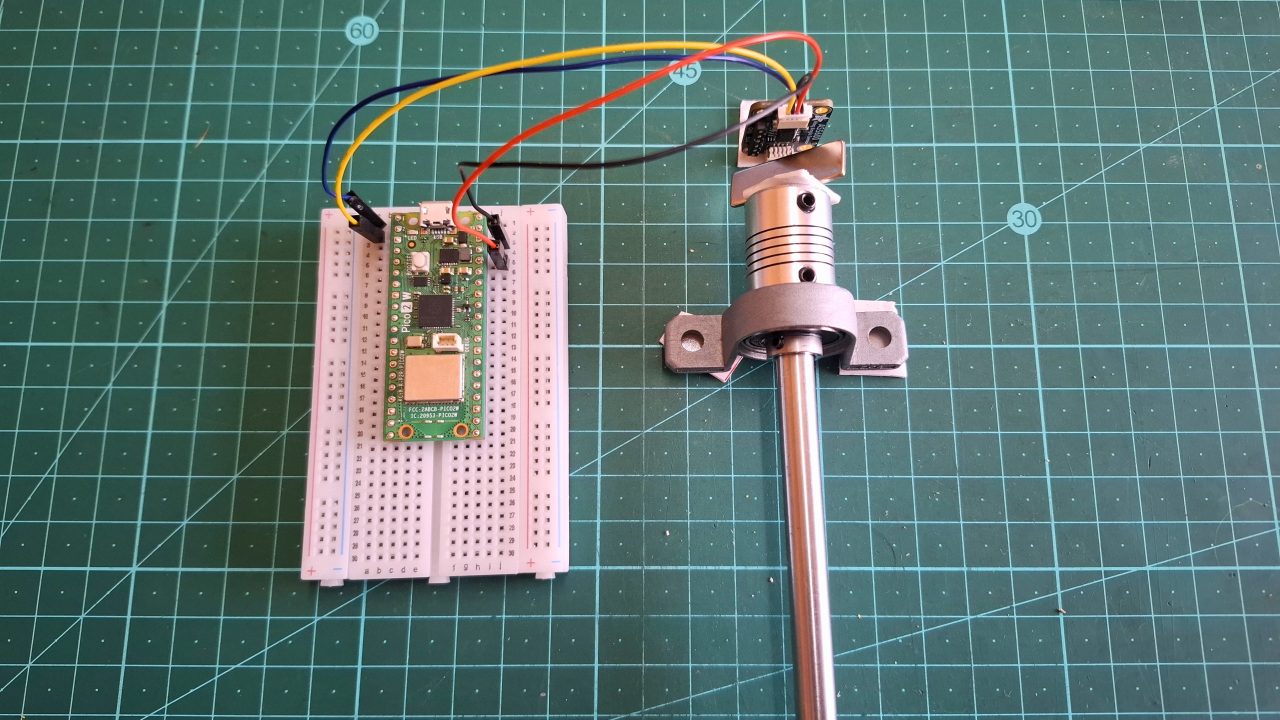
Below is just a little script for using the AS5600 as a volume controller on your pc as a beginner project using circuitpython. Ignore the rod attached to the magnet in the photo beneath, it’s from an upcoming project that we’ve been super excited to share.
					import time
import board
import busio
import usb_hid
from adafruit_hid.consumer_control import ConsumerControl
from adafruit_hid.consumer_control_code import ConsumerControlCode
import adafruit_as5600

# Give the host computer's USB port time to recognize the Pico as an HID device
time.sleep(2.0)

# Initialize USB keyboard control
try:
    cc = ConsumerControl(usb_hid.devices)
except ValueError as e:
    print("USB HID not ready yet. Try unplugging and replugging the Pico.")
    raise e

# Initialize explicit I2C Bus on GP4 (SCL) and GP5 (SDA)
i2c = busio.I2C(scl=board.GP1, sda=board.GP0)

# Connect the sensor using the official Adafruit Driver
sensor = adafruit_as5600.AS5600(i2c)

# Project parameters
dead_zone = 25
last_position = sensor.raw_angle

print("Magnetic Volume Control Active! Turn the dial to adjust PC volume.")

while True:
    current_position = sensor.raw_angle

    if current_position is None or last_position is None:
        last_position = current_position
        continue

    # Calculate raw distance turned
    diff = current_position - last_position

    # Handle the 360-degree boundary wrap-around (0 <-> 4095)
    if diff > 2048:
        diff -= 4096
    elif diff < -2048:
        diff += 4096

    # If rotation exceeds our dead zone threshold, trigger volume change
    if abs(diff) > dead_zone:
        if diff > 0:
            print("Volume Up 🔊")
            cc.send(ConsumerControlCode.VOLUME_INCREMENT)
        else:
            print("Volume Down 🔉")
            cc.send(ConsumerControlCode.VOLUME_DECREMENT)

        # Update our tracking reference point
        last_position = current_position

    # Poll every 20 milliseconds for incredibly responsive tracking
    time.sleep(0.02)
Conclusion
For projects where mechanical wear, dust, or long-term reliability are a concern, the AS5600 is a straightforward upgrade over traditional potentiometers and encoders. It’s simple to wire up, easy to code against thanks to broad driver support, and gives you clean, absolute angle data with no moving parts to fail.
Have you used the AS5600 in a build? We’d love to see what you’ve made, share it with us, or browse PiShop’s full range of STEMMA QT / Qwiic boards for your next project.