
Stop guessing how much battery you’ve got left | MAX17048 fuel gauge
Beginner, Feeds, News & Feeds, Other, Projects, Resources, Skills, Tutorial adafruit, beginner, fuel guage, MAX17048, raspberry pi, sensors 1
Unlike the fuel gauge in your car, this one might be a lot less distressing to look at.
Lots of our projects run on battery power, especially with how easily accessible these tiny Li-Po batteries have become. However, there is a potential problem you might run into if your project depends on battery power: how much charge does your battery have left?
Now, this isn’t impossible to try and estimate. A lithium battery’s level of charge corresponds to its voltage: a full battery runs at about 4.2V, and a dead battery is around 3.0V.
Where this does get tricky is that this is not a linear relationship. The best way to demonstrate this is probably by this graph:
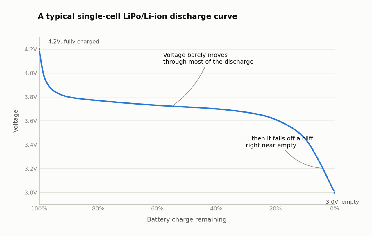
As you can see, the points between 4.2V (100% capacity remaining) and 3.0V (basically 0% remaining) don’t fall on a straight line, instead following a curve.
This makes a precise estimate about how much battery capacity you have left a lot more tricky, and it’s easy to get wrong. Get it wrong and your project won’t warn you. It’ll just die on you.
The Solution and How It Works
This is why chips like the MAX17048 fuel gauge come in. It uses an algorithm called ModelGauge to work out the charge percentage from how the voltage behaves, without you needing to feed it the battery’s capacity or build a curve yourself. All you have to do is connect your battery on the one end and your microcontroller or single-board computer on the other end, and it tells your project how much battery is left.
Now if you go looking for just a MAX17048, you’ll find a chip 2mm by 2mm in size. Hardly something that will work with a breadboard. That’s probably why Adafruit went ahead and put this on a breakout board.
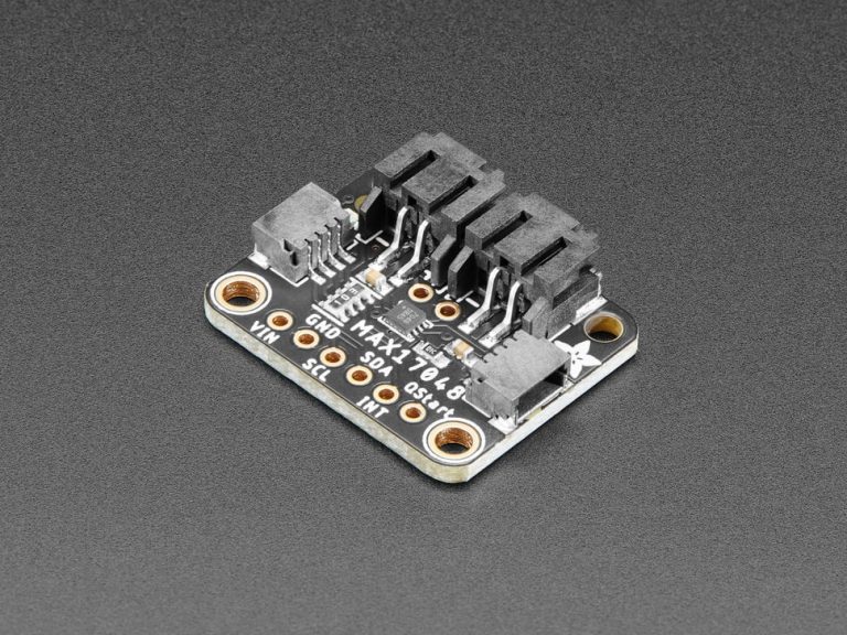
This board conveniently gives us a good number of connection options. You’ll see the two STEMMA QT connectors on either side of the board, for connecting to your existing STEMMA devices directly, rather than I2C wiring to figure out yourself.
Then there are two larger JST PH connectors at the top. These are connected to each other and it’s where your battery connects.
You can connect the battery to either of these connectors, and the other one then passes power from the battery through to your project.
Finally, there are six points at the bottom if you’d rather wire it up yourself: VIN, GND, SCL and SDA (for I2C), INT and QStart.
Two of these are worth a mention on their own. INT gives you an interrupt signal when the battery’s voltage or charge percentage drops below a threshold you set, handy for setting up a low battery alert without having to poll it yourself.
QStart lets you reset the module through hardware, instead of using I2C and even has a little power LED to tell you when it’s on.
This little board can be used with a lot of devices and the options are truly vast. For more information on how to use this module for your specific application, I would recommend looking at Adafruit’s own guide on how to use this. It goes through the physical pinout, code for Python and CircuitPython, wiring diagrams and instructions for a decent number of devices.
Where You Can Find It
If this module sounds perfect for one of your projects, you can get it from our website and if you’re putting a project together from scratch, a few things from the shop pair nicely with this:
- You’ll need an actual battery to plug into it. The Battery LiPo 800mAh 3.7V is a good general-purpose size to start with.
- You’ll also want a way to charge that battery once it runs down. The LiPo Amigo Pro charges over USB-C and can power your project and charge the battery at the same time.
- If you’re connecting to a STEMMA QT or Qwiic board, grab a STEMMA QT cable so you can skip the soldering.
Conclusion
If you have any components that you’d like use to do a write-up on, let us know in the comments! We’d love to hear your suggestions and the projects that you want to use them for!

2026-09-29 @ 18:06
My previous experience with similar components showed that extreme temperature fluctuations severely impact the battery life. This specific model performs best under steady operating conditions.