Don’t Fry Your Pi! How Level Shifters Protect 3.3V GPIO Pins
Beginner, News, News & Feeds, Resources, Skills, Tutorial component, level shifter, raspberry pi, sensors, Tech 0
If you’ve ever tried to connect a Raspberry Pi to a sensor or module built for 5V logic, you’ve probably run into a frustrating problem: the Pi’s GPIO pins are only rated for 3.3V, and feeding them 5V can damage them permanently. The same headache pops up any time you’re mixing microcontrollers and components that don’t speak the same voltage — whether that’s an Arduino talking to a 12V relay, or a Pico reading data from an older 5V sensor.
The fix is a small, unglamorous component called a logic level shifter (or level converter), and once you understand what it’s doing, it becomes one of those tools you reach for constantly. At its core, a bidirectional level shifter uses a MOSFET as a kind of voltage-aware switch between two sides of a circuit.
Let’s break down how it works, how to wire one up, and a few real projects where you’ll want one on hand.
Microcontrollers & Single-board Computers
The GPIO pins on Raspberry Pi SBCs and Pi Pico microcontrollers run at 3.3V, which is notably lower than what a lot of common sensors and modules expect.
Connecting a 5V sensor up to your board directly can cause problems in both directions. If the sensor expects a 5V signal but only receives 3.3V from the Pi, it might not perform as expected and could even be damaged over time. Conversely, feeding 5V directly into GPIO pins that normally operate at 3.3V will almost certainly damage the board, and might destroy it entirely.
The solution: Logic Level Shifters
- Get yours at PiShop Africa: 4-Channel Logic Level Shifter
- Compatible platforms: Any microcontroller or SBC board
How It Shifts Gears
Logic level shifters are electronically quite simple, at their core, it’s just an N-channel MOSFET connected between the high and low side.
A MOSFET is essentially an electronically actuated switch. Apply a small voltage across the gate and source, and the MOSFET switches on, allowing current to flow between the source and drain pins. Remove the voltage from the gate, and the MOSFET switches off.
Logic level converters put this mechanism to clever use for bidirectional communication. Each side of the channel has its own pull-up resistor (to 3.3V on the low side, to 5V on the high side), and the MOSFET’s gate is tied to the low-voltage rail. When either side pulls its line low, the MOSFET conducts and drags the other side low too, so a 3.3V microcontroller pulling its line low will pull the 5V side low as well, and vice versa. When neither side is actively pulling low, each side’s own pull-up resistor lets it float back up to its own native voltage, 3.3V on one side, 5V on the other. That’s what lets a signal travel in either direction while each side still only ever sees its own correct voltage.
This might sound somewhat complicated, but really, you don’t have to worry about the exact details, all the wiring has already been done for us on a handy little breadboard-compatible PCB.
Wiring & Hardware Setup
Wiring this up is actually very simple.
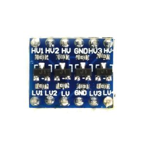
On closer inspection of the board, you’ll see markings on one side like LV, LV1, LV2, LV3, LV4, and on the other side, markings like HV, HV1, HV2, HV3, HV4. On both sides, there’s also a GND marking.
Let’s start with the easiest one: GND simply means ground. These two pins, one on each end of the board, are directly connected to each other and should be connected to the ground pins of both your microcontroller/Pi and your sensor.
LV and HV stand for “Low Voltage” and “High Voltage” respectively.
LVconnects to your low voltage supply — in our example, the 3.3V GPIO pin.HVconnects to your high voltage supply — whatever source you’re using to power your sensor. This could be the 5V GPIO pin on your Raspberry Pi or Pico.
From there, each LV(n) pin pairs up with the corresponding HV(n) pin. In other words: LV1 is connected, via its MOSFET, to HV1, LV2 to HV2, and so on.
All you have to do is connect the LV(n) pin to the GPIO pin on your Pi/Pico, and the corresponding HV(n) pin to your sensor pin. That’s it.
What Can You Build With It?
There are endless uses for these boards, and you’ll find the underlying MOSFET circuit in thousands of electronic products. Here are a few concrete examples using real components you can pick up alongside your level shifter:
- Connecting a 3.3V GPIO pin to a 5V sensor – a great example is the HC-SR04 Ultrasonic Distance Sensor. It’s a hugely popular, low-cost distance sensor, but it runs on 5V logic, including its
Echooutput, which talks straight back to your board. Feed that 5VEchosignal into a 3.3V Raspberry Pi GPIO pin without a level shifter, and you risk damaging the pin. Route it through a level shifter first, and it’s perfectly safe. - Driving 5V relays from a 3.3V GPIO pin – boards like the Two Channel 5V DC Relay Module or the Four Channel 5V DC Relay Module are designed to be triggered by 5V logic. A level shifter lets you drive them cleanly from a 3.3V Pi or Pico, so you can safely switch lamps, pumps, motors, and other higher-power appliances from your project.
- Going even higher – the same trick works for other voltage combinations too. For example, connecting a 5V pin on an Arduino to a 12V relay coil, using a level shifter rated for that voltage range.
Conclusion
Next time you’re working on a project, keep level shifters in the back of your mind whenever the topic of mismatched voltage levels comes up.
One important note: these converters are digital. That means they can only convert a high or low voltage, nothing in between. Analogue signals are an entirely different topic, which we might dive into in a future post if there’s enough feedback requesting it.