
Pi Stop – Traffic Light Add-on for Raspberry Pi
After running the official documentation and finding that they have not yet been updated, and far more complicated than what they should be, I became determined to find a better solution to using the Pi-Stop.
The first step in the documentation would be to install the GPIO module for scratch, but I have found that this is now pre-installed. Which is great. The next step would be to find the latest example of using the Raspberry Pis GPIO pins in Scratch. I made use of the following tutorial provided by the Raspberry Pi Foundation as a base Physical computing with scratch. Granted, it is noted that the tutorial has been decommissioned, but still works.
The Hardware:
A Raspberry Pi, Power supply, SD card (16GB or bigger) with Raspberry Pi OS loaded on and optionally an enclosure that exposes your GPIO pins
You could also look at one of our great essentials kits, where we provide you with everything you need to get started.
Finally you will need a Pi-Stop
The software:
We will assume that you have already gotten your Raspberry Pi setup and running. If you haven’t, you can follow along with our First look tutorial before continuing.
The official docs provided:
- Explore and Challenge Scratch GPIO: Pi-Stop First Steps: If you’ve not used Scratch before, this will provide a quick introduction to building your first Scratch GPIO program. (pdf)
- Explore and Challenge Scratch GPIO: Pi-Stop Traffic Sequence – Create your own traffic light sequence and learn how to use Scratch GPIO with the Pi-Stop. (pdf)
- Explore and Challenge Scratch GPIO: Pi-Stop Reaction Game – How fast are your reflexes? Test your reaction time with the Pi-Stop Reaction game. (pdf)
- Explore and Challenge Scratch GPIO: Pi-Stop Simon Memory Game – Challenge your memory and get the highest score! (pdf)
Lets recreate the Pi-Stop First steps:
We will begin with installing scratch on your Raspberry PI using the built in recommended software installer.

Start by clicking on start (the Raspberry Pi Logo), scroll down to preferences, and then selecting Recommended Software.

A menu will open showing all recommendations. Since we know we are looking for a programming IDE, I clicked on the Programming menu on the left, and search for Scratch. Selecting the checkbox on the right so that it is ticked and will show that it will be installed. Then click on apply.

After a short install, you will receive a notification that Scratch has been installed.

Once you click close, you will be prompted to reboot.

Instead, select No, and power off your Pi at this point if you have not yet installed your Pi-Stop, if you have you can simply click yes to reboot. While your Pi is off, we can install our Pi-Stop. I opted to make use of the Location A shown in the origional documentation. This would install the Pi-Stop in pins GND, GPIO25, GPIO8 and GPIO7. If you choose another location, be sure to adapt then in the code blocks as well.

The latest GPIO library also uses the general GPIO pinout numbering, so you do not need to use the physical pins anymore. Then you can switch your Pi back on.
Finally we are ready to get started. Open Scratch IDE by going back to the start menu (the Raspberry Pi Logo), then programming. You will find Scratch now located here.

We will focus on the control blocks so you can select them now.

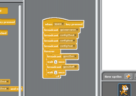
First I wanted to make sure that the sprite starts when I choose to do so. In the example provided in the Foundation project, they used “When Flag clicked”, you can use that, but I chose the “When space key pressed” instead. I’m sure both would work the same.

Then, like with any programming language, we need to setup the GPIO pins we want to use.

This is done with the broadcast blocks. We start by starting the GPIO server. Select a new broadcast block and on the dropdown select new/edit, and type in gpioserveron in the provided space. Then we want to configure our 3 pins as output pins. Again select a new breadcast block, select new/edit and type in config25out, and repeat for the other 2 pins being used.

Then we use the forever block to make our code run in a continoues loop. This is added to our setup block, and inside we will add what should continue to happen.

Starting with our first LED (the green one in my case), let’s test it. Click on the code block so that it has a white highlight around it.
Then click on the green flag to start your program, and press space.

We should now have a blinking LED. And with this we have also completed the first steps example.
Pi-Stop Traffic Sequence
Moving on to the second example.
We will start with our setup again. This time Starting with the “when GreenFlag clicked” start block, and setting up the same 3 pins as in our previous example.

Then we want to make 3 more start blocks. The first to represent “GO”, next is “HALT” and then “STOP”. We will start with 3 “When I receive” blocks.

Here we want to specify what should happen in each of these instances. When the GO command is set, then the green LED should be on, and the other 2 should be off. For HALT, we want our yellow LED on and the other 2 should be off. For STOP the Red should be on and the other 2 should be off. Remember following our setup for Location A, GPIO25 is Green, GPIO7 is Red and GPIO8 is yellow.

Now we can move back to our main block and setup our interval of when our LEDs should change color.

Thinking about how a traffic light would function, you would be allowed to drive for a period of time, get a yellow light for a much shorter time, and then a red light. The red light should be long enough for the green and yellow lights to finish in the other direction. Lets press play and watch our traffic light go. You can change your wait blocks to any time you want.
I will not be going through the next 2 projects. Hopefully this was enough to show you how to interpret the official guides, so you can adjust them yourself.
If you have any questions or comments, email us at [email protected]


