Making Pedals for our Racing Sim | DIY Racing Sim Pedals
3D Printing, Beginner, Other, PiShop, Platforms, Projects, Raspberry Pi Pico, Resources, Robotics, Skills, Tutorial 0
What’s a keyboard without a mouse? What’s a TV without sound output? What’s a steering wheel without some pedals? We’ve had a severe lackage of pedals in our racing sim setup and that’s what we’ve set out to accomplish in the last 2 grueling weeks but at what cost. Burns from soldering, cut’s from playing with springs, sore palms from not giving enough clearance on laser cuts. It was all worth it though.
Today I’ll be going over what you’ll need to build your own pedals from scratch as well as supply the necessary files if you want to build it exactly like mine!
What You'll Need
Please note that this is a continuation of our previous Racing Wheel project, refer to that project for original scripts and board used. As I move through the instructions I’ll describe how you can accomplish certain steps even if you don’t have a 3D printer or laser cutter for specific components, for now, here’s everything that I used and needed:
- 1 x 10k Potentiometer
- 1 x Compression Spring
- 1 x 400mm T8 Linear Shaft
- 2 x 8mm Pillow Block Bearing
- 1 x 8mm Flange Pillow Block Bearing
- 1 x GT2 Belt
- 2 x 8mm Shaft coupler
- 3 x Male to Female Jumper Cable 200mm
- 4 x M5 Nuts
- 4 x M5 x 35 Allen Cap Screws
- 2 x M5 x 12 Allen Cap Screws
- Laser cutter (Creality Falcon2 Pro S 40W if you don’t already have one)
- 3D Printer (Creality SparkX i7)
A DIY Racing Sim Rig using components from Raspberry Pi and Arduino with sensors such as the Adafruit As5600
How To Build The Pedal
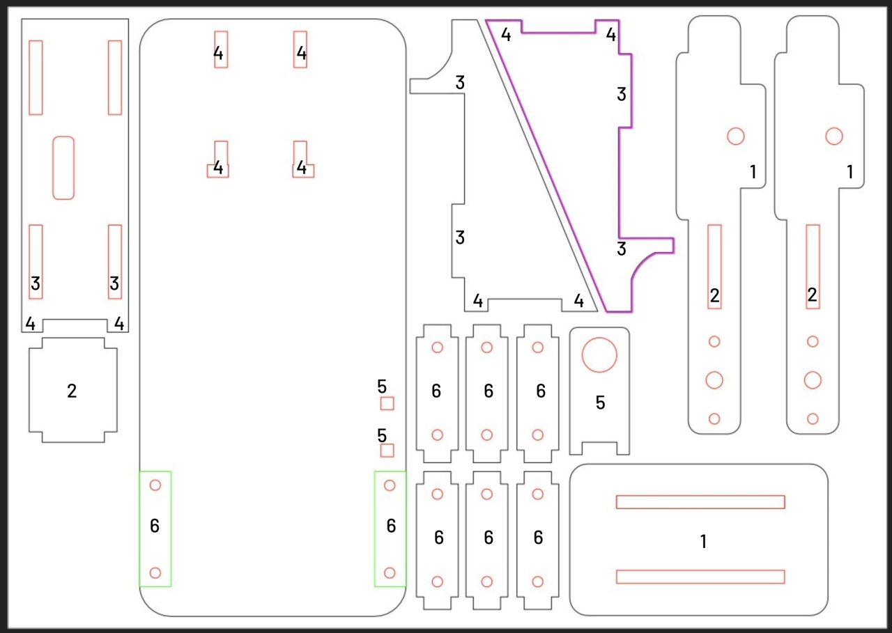
You’ll find that with the laser cut file I have number the components that attach together. Please keep in mind that you don’t need all the bearings and specific sized screws if you aren’t following the laser cut build, you just need some scrap wood, a drill and the shaft for each section of this build.
Below you’ll find a picture with the parts numbered together but I’ll have a video and IRL pics to support it just below it.
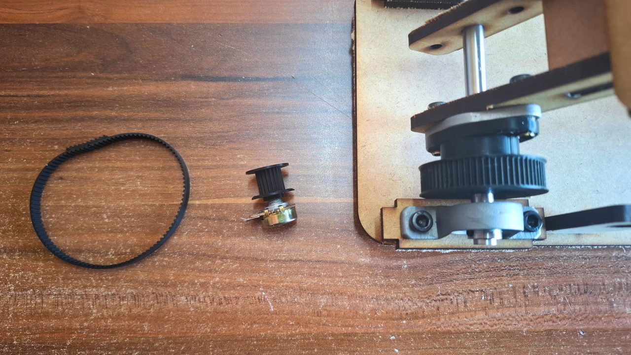
The 3D printed pieces are attached to the potentiometer and the bearing on the shaft. The science behind this build goes as follows: big gear on the fulcrum of the pedal turns the smaller gear a bit more than it would a bigger gear about 20° more to be exact. This gives us a bit more wiggle room for adjustability in game.
Last but not least on the physical end of this project is the timing belt. I can’t say that I’ve figured out how to use timing belts properly just yet, I kind of eye-balled the length and it worked out. I attached both ends of the timing belt by cutting a smaller piece extra and super glued everything together, also seen in the picture below.
The Code
As I said before, this project is a continuation of the Racing wheel project so I’ll just be adding code to the code.py file of the project. To start, connect the potentiometer pins as stated below. With the potentiometer dial facing away from you and the pins facing downwards, Pin 1 is on the left and Pin 3 is on the right.
Pin 1 to 3v3 out
Pin 2 to GP26
Pin 3 to GND
Don’t worry if you have Pin 1 and Pin 3 swapped around it should just measure the potentiometer backwards. You can test the data from the potentiometer using the follow script.
					import board
import analogio
import time

throttle_adc = analogio.AnalogIn(board.GP26)

print("--- PEDAL RAW CALIBRATION RUNNING ---")

while True:
    raw = throttle_adc.value  # Reads 0 to 65535

    # Calculate approximate voltage on GP26 (0.0V to 3.3V)
    voltage = (raw * 3.3) / 65535

    print(f"Raw ADC Value: {raw:<5} | Voltage: {voltage:.2f}V")
    time.sleep(0.1)
While using this script, make sure to write down the value for when the pedal is at rest and when it is being floored. You’ll need these values for the code.py script. To update the specific values needed you can follow the next 2 steps.
Step 1: Update the Calibration Constants
Near the top of code.py, locate the Calibration Constants section and replace the numbers with their measured values:
					# ==========================================
# CALIBRATION CONSTANTS (CHANGE THESE FOR YOUR RIG)
# ==========================================
# 1. Enter the raw ADC number measured when your foot is completely OFF the pedal
PEDAL_REST = 27900

# 2. Enter the raw ADC number measured when the pedal is FLOORED to the ground
PEDAL_FLOORED = 8600
Pro Tip: Adding or subtracting a small 100 to 300-point buffer to those constants prevents “signal flicker.”
If your rest value flickers around
27900, setPEDAL_REST = 27700so the signal comfortably settles at 0%.If your floored value flickers around
8600, setPEDAL_FLOORED = 8800so you always hit 100% full throttle.
Step 2: Use the Auto-Inverting Scaling Function
Depending on how your gears or levers rotate the potentiometer, the raw values will either sweep down (e.g. 28,000 to 8,000) or sweep up (e.g. 8,000 to 28,000).
To make sure games like RaceRoom always receive a clean 0 (rest) to 255 (floored) byte array without needing extra setting flips, they should use this dynamic scaling function:
					def scale_pedal_calibrated(raw_val, rest_val, floored_val):
    """
    Automatically scales any pedal setup (whether raw values go UP or DOWN)
    into a clean 0 to 255 byte array for Windows.
    """
    # 1. SWEEP DOWN SETUP (Rest is higher than Floored)
    if rest_val > floored_val:
        if raw_val > rest_val: raw_val = rest_val
        if raw_val < floored_val: raw_val = floored_val
        scaled = int(((rest_val - raw_val) / (rest_val - floored_val)) * 255)

    # 2. SWEEP UP SETUP (Rest is lower than Floored)
    else:
        if raw_val < rest_val: raw_val = rest_val
        if raw_val > floored_val: raw_val = floored_val
        scaled = int(((raw_val - rest_val) / (floored_val - rest_val)) * 255)

    return max(0, min(255, scaled))
These steps essentially make it so that you don’t need to keep switching or resoldering wires and it plugs cleanly into windows.
code.py
This script is designed for working with 1 pedal, you can find the version that works with 2 if you feel like doing the manual labour again to create a break pedal.
					import board
import busio
import digitalio
import analogio
import time
import usb_hid
import adafruit_as5600

# ==========================================
# 1. HARDWARE SETUP
# ==========================================
# Steering Wheel: I2C connection to AS5600 (SCL -> GP1, SDA -> GP0)
i2c = busio.I2C(board.GP1, board.GP0)
as5600 = adafruit_as5600.AS5600(i2c)

# Accelerator Pedal: 10k Potentiometer Wiper on GP26 (ADC0)
throttle_adc = analogio.AnalogIn(board.GP26)

def setup_btn(pin):
    btn = digitalio.DigitalInOut(pin)
    btn.direction = digitalio.Direction.INPUT
    btn.pull = digitalio.Pull.UP
    return btn

# 8 Button Layout (GP6 through GP13)
buttons = [
    setup_btn(board.GP6),   # Button 1
    setup_btn(board.GP7),   # Button 2
    setup_btn(board.GP8),   # Button 3
    setup_btn(board.GP9),   # Button 4
    setup_btn(board.GP10),  # Shifter Left
    setup_btn(board.GP11),  # Shifter Right
    setup_btn(board.GP12),  # Button 7
    setup_btn(board.GP13)   # Button 8
]

# ==========================================
# 2. CALIBRATION CONSTANTS (YOUR MEASURED DATA)
# ==========================================
# Rest is around 28,000 | Floored is around 8,700
# We add a small 300-point buffer so the pedal cleanly hits 0% and 100%
THROTTLE_REST    = 27700  # Map to 0 byte (Released)
THROTTLE_FLOORED = 8900   # Map to 255 byte (Full Throttle)

def scale_wheel(val):
    """Scales 12-bit AS5600 reading (0-4095) down to 8-bit HID (0-255)."""
    REVERSED = False
    wheel_offset = 2048  # Physical center alignment point

    calibrated_val = (val - wheel_offset) % 4096
    if REVERSED:
        calibrated_val = 4095 - calibrated_val

    s = int((calibrated_val / 4095) * 255)
    return max(0, min(255, s))

def scale_pedal_calibrated(raw_val, rest_val, floored_val):
    """
    Directly converts a reverse-sweeping ADC signal (High rest, Low floored)
    into a clean 0 to 255 forward byte array.
    """
    # 1. Clamp raw reading within physical boundaries
    if raw_val > rest_val:
        raw_val = rest_val
    if raw_val < floored_val:
        raw_val = floored_val

    # 2. Reverse scaling math: High raw = 0 (Rest), Low raw = 255 (Floored)
    scaled = int(((rest_val - raw_val) / (rest_val - floored_val)) * 255)

    return max(0, min(255, scaled))

# Locate USB Gamepad Interface
gamepad_dev = None
for device in usb_hid.devices:
    if device.usage == 0x05:
        gamepad_dev = device
        break

print("✅ Calibrated Rig Active: Steering (AS5600) + Accelerator (GP26) + 8 Buttons")

# ==========================================
# 3. MAIN RUNTIME LOOP (100Hz)
# ==========================================
while True:
    if gamepad_dev:
        # 1. Process Steering (X-Axis)
        raw_angle = as5600.angle
        if raw_angle < 10: raw_angle = 0
        if raw_angle > 4085: raw_angle = 4095
        x_wheel = scale_wheel(raw_angle)

        # 2. Process Accelerator Pedal (Y-Axis)
        y_throttle = scale_pedal_calibrated(
            throttle_adc.value,
            THROTTLE_REST,
            THROTTLE_FLOORED
        )

        # 3. Zero-out unused axis channels (Brake / Rz) to prevent in-game telemetry noise
        z_brake = 0
        rz_unused = 0

        # 4. Pack Buttons into bitwise byte array
        b_low = 0
        for idx, btn in enumerate(buttons):
            if not btn.value:  # Active LOW (pressed)
                b_low |= (1 << idx)
        b_high = 0

        # 5. Dispatch USB Report: [Buttons_Low, Buttons_High, Steering, Throttle, Brake, Unused]
        report = bytearray([b_low, b_high, x_wheel, y_throttle, z_brake, rz_unused])

        try:
            gamepad_dev.send_report(report)
        except Exception:
            pass

    time.sleep(0.01)  # Locked 100Hz Polling Rate
Conclusion
That’s that. It was a perilous journey for me, you can see the plaster and a few cuts on my fingers in the video but all worth it in my opinion. I can now somewhat enjoy my truck simulators, all I need is something to change gears. I don’t think I mentioned this but if you want breaks you’ll have to do this twice! I’d recommend getting something soft bit firm like foam for emersion on the break pedal.
Have you ever created something like a racing sim before? We’d love to hear about it, just share it in the comments or mention us on socials, you can find those below as well.