How to Smart Lamp with Pico 2W
Beginner, Getting Started, Home Automation, PiShop, Platforms, Projects, Raspberry Pi Pico, Resources, Skills, Tutorial esphome, getting started, home automation, raspberry pi pico, raspberry pi pico 2w, Tech 0
No lamps were harmed in the making of these video… maybe.
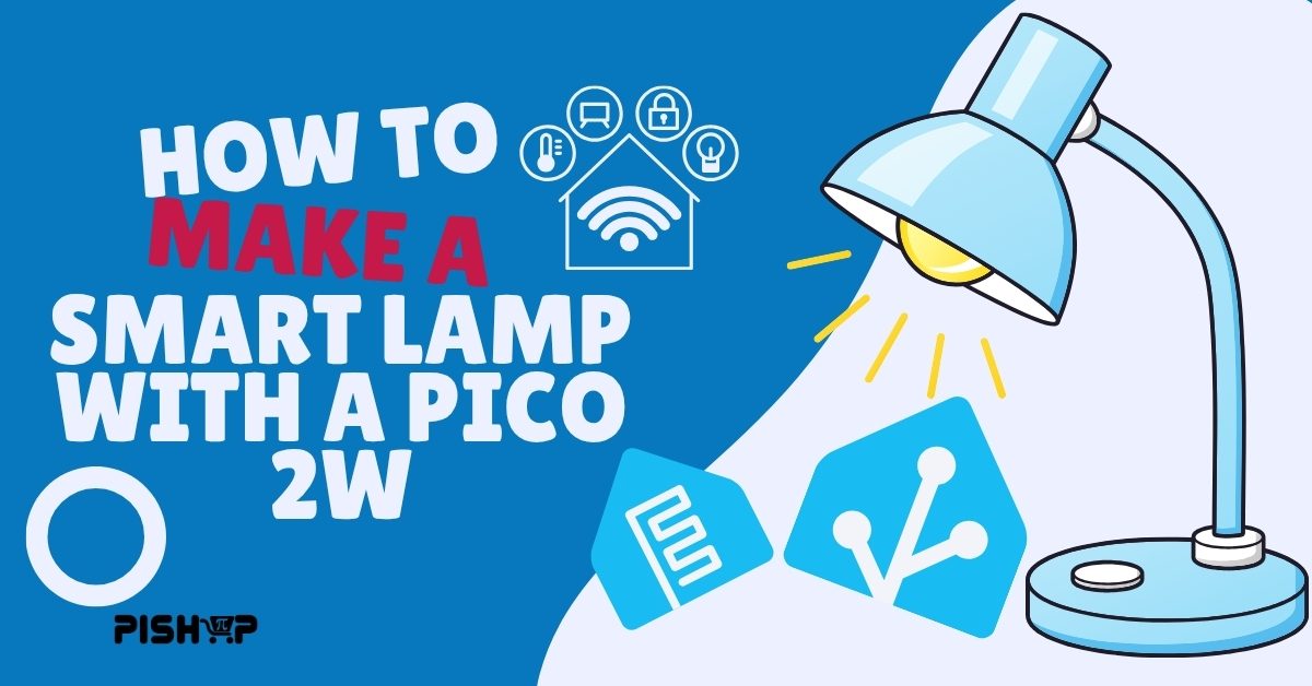
Ever wanted to get into the home automation hobby but the prices scared you off, especially on the lightbulbs or you just don’t like the bulky smart plugs hanging off your walls? Because Same, that’s why today we’ll be going over the process of turning a normal desk lamp into a Raspberry Pi Pico 2W powered smart lamp using ESPHome and Home Assistant.
We’ll cover both the circuit layout, soldering and setup as well as the ESPHome setup. And for this project you’ll need some basic soldering skills as well as some surface level knowledge on yaml files.Building the control into the lamp itself, using a relay driven by a microcontroller, avoids that problem entirely: the light itself can be a plain, dumb bulb, and all the “smart” logic lives upstream of it, always powered.
The bigger design decision in this build is going DC-only. Instead of switching your lamp’s mains AC circuit with the relay (the “obvious” way to do this), the whole build, Pico, relay, and even the bulb, runs on low-voltage DC, and the only component that ever touches mains electricity is a sealed, pre-built wall adapter. That removes the riskiest part of a typical smart-lamp build: opening up a lamp’s mains wiring and running control electronics right next to it.
What You'll Need
It’s gonna be a pretty budget friendly project today with the highest costs going for the Pico 2W, the power supply and a new lightbulb depending on the lamp you have.
- Raspberry Pi Pico 2 W
- 3V relay module (1-channel, active H/L, optocoupler-isolated)
- AC to DC 12V 2A power supply adapter
- 12V-to-5V buck converter (e.g. a UBEC-style step-down module)
- Micro-USB cable (for the Pico 2 W)
- 12V DC LED bulb, E27/E26 screw base
- Jumper wires (male-to-female / female-to-female)
- DC barrel connector or pigtail
- Small project enclosure
- Heat-shrink tubing or wire nuts
- Wire strippers, small screwdriver
- Multimeter
A couple of these choices are mildly worth explaining. The 3V relay module was picked specifically because it wants exactly 3.3V on its logic side, which happens to be exactly what the Pico’s 3V3(OUT) pin already provides, with no extra regulation needed. And the 12V DC LED bulb is the piece that makes the whole DC-only design possible: it’s a standard screw-base bulb, but built for low-voltage solar and off-grid lighting setups, so it drops straight into a normal lamp socket without needing any mains voltage at all.
Understanding The Circuit
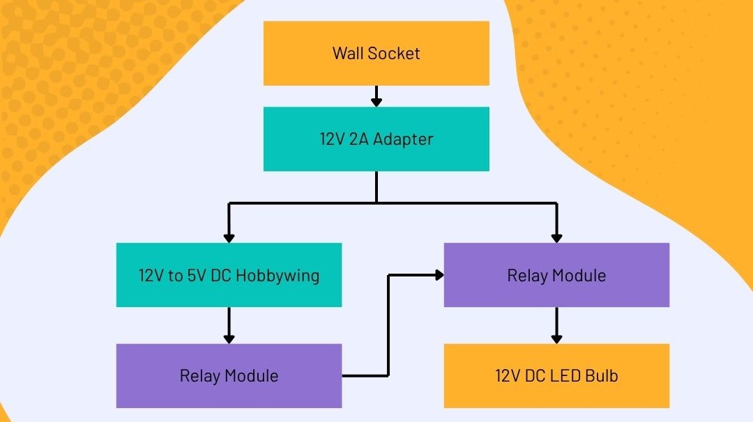
It helps to think of this build as two separate circuits sharing one power source:
- The power path: wall socket → 12V adapter → buck converter → Pico (via USB)
- The control path: Pico’s 3.3V + a GPIO pin → relay → 12V DC bulb
Mains electricity only exists between the wall socket and the 12V adapter, a sealed, factory-built unit. Everything past that point, including the bulb itself, runs on 12V or 5V DC. The relay’s job is simple: it sits in the bulb’s positive supply line, and the Pico tells it when to open or close that connection.
Wiring the Relay
The relay board has two electrically isolated sides, and it’s important not to mix them up:
Control side — connects to the Pico:
DC+→ Pico3V3(OUT)DC-→ PicoGNDIN1→ a free Pico GPIO pin
Switched side — connects to the 12V power and the bulb:
COM→ 12V supply positiveNO→ bulb positive leadNC→ not used
The relay also has a jumper to select active-high or active-low triggering. Set it to active high. On boot or reset, GPIO pins default to a low state before the firmware takes control — with active-high triggering, that means the relay (and the lamp) defaults to off during that window, rather than briefly and unexpectedly turning on.
Wiring the Buck Converter
The buck converter takes the 12V adapter’s output and steps it down to 5V for the Pico:
- Input + → 12V adapter positive
- Input – → 12V adapter negative
- Output + → Pico
VSYS - Output – → Pico
GND
If your buck converter has a voltage-select jumper, double-check it’s set to 5V, not a higher voltage. Before connecting it to the Pico, measure the output with a multimeter to confirm it’s actually reading 5V — cheap insurance against a damaged board.
Installing ESPHome
If you’re running Home Assistant, install the ESPHome add-on from Settings → Add-ons → Add-on Store.
After installing ESPHome open the webUI and click on Add device. Follow the process and enter the necessary details such as Wifi credentials and the board being used. Once finished, open the device and you’ll see the yaml file on the right hand side of your monitor

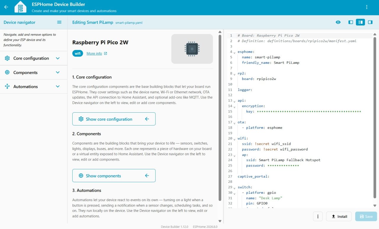
Add the follow to your yaml file at the end of the script:
					switch:
  - platform: gpio
    name: "Desk Lamp"
    pin: GPIO0
    inverted: false
Then click on install, then advanced options, then download firmware binary. This will create a file that you can drag and drop into your Pico 2W in bootsel mode.
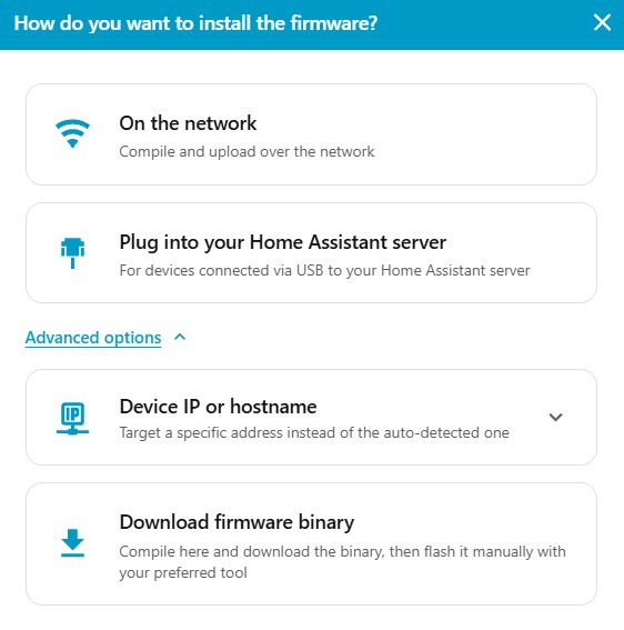
You can find more details below for the setup process on a Raspberry Pi Pico w.
Before Running: Testing & Troubleshooting
Before powering on for the first time, use a multimeter to confirm:
- The 12V adapter is actually outputting ~12V
- The buck converter’s output is ~5V, not 6V
- No shorts between positive and negative anywhere in the DC wiring
Once powered on, check that the Pico joins WiFi and shows up in the ESPHome dashboard, and that toggling the “Desk Lamp” switch in Home Assistant produces an audible click from the relay and turns the bulb on and off.
Common issues to check if something’s not working:
- Relay clicks but the bulb doesn’t respond – check polarity and connections on the switched side.
- Switch is inverted (on turns the lamp off) – check the relay’s jumper matches your
inverted:setting in YAML. - Pico won’t join WiFi – confirm the network is 2.4GHz, not 5GHz-only.
- No power at all – retrace the DC path from the 12V adapter through the buck converter to
VSYS.
Conclusion
Once you’ve checked that everything is up and working, you can wait for the Pico 2W to connect to your Home Assistant and from there the world is yours! Here’s some natural steps following this kind of project:
- Automations: turn the lamp on at sunset, off at a set bedtime, or based on presence detection.
- A physical override switch: wire a simple inline switch so the lamp can still be controlled manually if the Pico ever loses power or crashes.
- Dimming: this build is on/off only – adding brightness control would mean swapping the relay for a PWM-capable dimming module, a good follow-up project once the basic build is working.
Not too difficult of a project I’d say, the most annoying bit had to be soldering but I managed to survive that somehow, with only a few burns on my finger tips. Have you created any smart tech for your own home? If you have or if you have an interesting idea for one then make sure to share it in the comments or tag us on socials!