
A Power Button For Raspberry Pi, Courtesy Of Device Tree Overlays
As a standard feature of the Linux kernel; device tree overlays (DTOs) allow for easy enabling and configuration of features and drivers; such as those contained within the standard firmware of a Raspberry Pi system. Using these DTOs it’s trivial to set up features like as a soft power-off button; triggering an external power supply and enable drivers for everything from an external real-time clock (RTC) to various displays; sensors and audio devices; all without modifying the operating system or using custom scripts.
It’s also possible to add your own DTOs to create a custom overlay that combines multiple DTO commands into a single one; or create a custom device tree binary (DTB) for the target hardware. Essentially this DTB is loaded by the Linux kernel on boot to let it know which devices are connected and their configuration settings; very similar to what the BIOS component with x86-based architectures handles automatically.
Ultimately, the DTB concept and the use of overlays allow for easy configuration of such optional devices and GPIO pin settings; especially when made configurable through a simple text file as on the Raspberry Pi SBC platform.
THE LINUX DEVICE TREE
As noted earlier, the device tree is compiled into a binary that is handed to the kernel on boot. Contained in this device tree is the list of connected devices, their driver and other relevant settings. On platforms that do not use a BIOS-like system to auto-detect devices, like graphics cards and network cards, and for devices which do not have an auto-detect and auto-configuration option like I2C and SPI devices, the device tree has to be constructed in this manner.
The use of such an external device tree saves the trouble of recompiling the kernel with every hardware change; with a central DTB file for the system device configuration, like those provided for Raspberry Pi SBCs. Recompiling this DTB for any newly added or changed device would be as much hassle as recompiling the entire kernel. This is where overlays come into play.
After the DTB is loaded by the kernel, DTOs are applied, per the Linux kernel documentation on DTOs. The overlay itself is specified as a device tree source; compiled using the device tree compiler into a device tree binary overlay (DTBO) file. For the Raspberry Pi these DTBOs can be found just like the DTBs on the Raspberry Pi GitHub account.
SOFT POWER BUTTON
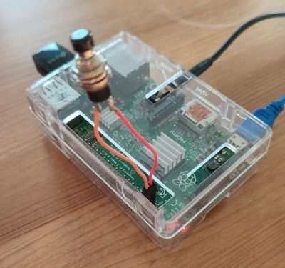
As a simple but rather useful example of what DTOs on Raspberry Pi SBCs can accomplish, let’s take a look at how to implement a soft power on and off button using nothing but a default Raspberry Pi OS image, a momentary (normally open) switch and some wiring to connect this switch to two pins on the GPIO header, as in the image on the right.
To make this work, there are two components at play here. The first concerns the soft power on. On Raspberry Pi boards, when the CPU is in halt state (powered, but CPU not running); GPIO3 is kept in high state due to an external pull-up resistor. Whenever GPIO3 is pulled low in this state, the CPU is resumed.
This is accomplished by putting our NO switch on GPIO3 and a ground (GND) pin. When the system enters the halt state and we push the button, GPIO3 is pulled low and the system resumes.
For soft power-off, we need to use the first overlay. Since we’ll be using GPIO3 also for powering off the system, we will add the following device tree overlay (dtoverlay) to /boot/config.txt:
dtoverlay=gpio-shutdown,gpio_pin=3,active_low=1,debounce=1500
gpio-shutdown
The gpio-shutdown DTO is described in the overlay README:
Name: gpio-shutdown
Info: Initiates a shutdown when GPIO pin changes. The given GPIO pin
is configured as an input key that generates KEY_POWER events.
This event is handled by systemd-logind by initiating a
shutdown.
If the system is booted when we trigger this event; it will thus act as if we pushed the ‘power’ button on a desktop system, turning the system off and halting the CPU.
Beyond the GPIO pin number; we can also configure the state of the pin when it should trigger the event (here when pulled low); and since we are using a mechanical switch we’d like to have a built-in debounce delay before the event is triggered.
Of course, since we can configure the GPIO pin here, we don’t necessarily have to use GPIO3 here; which may be desirable since GPIO3 is also the (non-remappable) I2C1 SCL pin, and losing access to the primary I2C bus could be a problem. Instead another GPIO pin (like 17) could be used; with the complication that using a single momentary switch as in the previous example would no longer be possible without jumping through some extra hoops.
gpio-poweroff
Another interesting power-related overlay is the gpio-poweroff one:
Name: gpio-poweroff
Info: Drives a GPIO high or low on poweroff (including halt). Using this
overlay interferes with the normal power-down sequence, preventing the
kernel from resetting the SoC (a necessary step in a normal power-off
or reboot). This also disables the ability to trigger a boot by driving
GPIO3 low.
When using an external power supply module, this signal is used to turn off power to the SBC; and likely shutdown the power supply itself until woken up again by some other signal. This could conceivably be useful in industrial and remote locations where some level of automation and/or power savings would be desirable.
Read More: https://hackaday.com/2022/04/04/a-power-button-for-raspberry-pi-courtesy-of-device-tree-overlays/


